Mechanical lifts (escalators and elevators) can be an invaluable resource to Fire Service personnel. But before their use is considered it is important that their design and construction is well understood. Only with this knowledge can an informedand accurate risk assessment of their use be satisfactorily be completed.
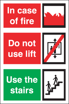
A dangerous misconception amongst many Fire fighters is that lifts with " Fire service over-rides" are Fire fighting lifts ...THEY ARE NOT!!!!!
History:
Lifts are key in the development of modern high rise buildings. Without them moving to high floors by staircases would have been too arduous.
Lifts (elevators) are first thought to have been constructed by the Romans over 2000 years ago. Until recent times these devices were crude and generally regarded as unsafe.
The invention of the Safety elevator (by Otis in 1853) is regarded as the turning point in the adoption of lifts as a safe and acceptable form of vertical transport in tall buildings. Otis lifts incorporated a mechanism that protected the occupants from uncontrolled descent should the lift cable fail. Ottis lifts are still in existence now, as a subsidiary of United Technologies Corporation (USA), who are the worlds largest vertical transport manufacturer.
Lifts are regarded as the safest form of vehicular transport in the world. In the UK there are various minimum design safety requirements usually encompassing British standards, or more recently European standards.
The current primary standards are BS-EN81 and BS5655
BS EN81 was approved by CEN on 21st February 1998. This new standard was optional until 1st July 1999 at which time it replaced and superseded the existing standards.
EN81-1:1998 Safety Rules for the construction and installation of lifts - Electric lifts - replaces BS 5655 Part 1 1986.
EN81-2:1998 Safety Rules for the construction and installation of lifts - Hydraulic lifts - replaces BS 5655 Part 2 1988.
Both new standards include the new measures required for compliance with the Lifts Regulations 1997 which came into full force also on 1st July 1999.
These documents have been accepted by BSI as British Standards.
The EN81 group of standards has been expanded to cover other related topics including;
- EN81-21: New passenger and goods lifts in existing buildings.
- EN81-28: Remote alarm on passenger and goods passenger lifts.
- EN81-70: Accessibility to lifts for persons including persons with disability.
- EN81-71: Vandal resistant lifts.
- EN81-72: Fire fighting lifts
- EN81-73: Behavior of lifts in the event of fire.
- EN81-80: Safety rules for the construction and installation of lifts
Many of the High rise buildings in the UK will have been built long before EN81 was enacted and in fact before BS5655 or even its predecessor BS2655 (approved in the early seventies).
Before BS-CP3 and BS2655 Lift design was a matter for architects, building design approval and customer requirement. There were some standards and design guides available but not in the format of nationally approved specifications. Many high rise tower blocks in the UK pre-date any nationally approved standard and as such may be laid out or function in unexpected ways. This must be investigated and borne in mind during any pre planning of lift usage at an incident.
Design:
In its simplest form a lift consists of a vertical shaft in which goods / people can be mechanically moved. Lifts are primarily powered by electricity and this in turn is used to create Kinetic rotational energy (as used in cable operated lifts) or Hydraulic Energy. In high rise accommodation by far the most common form of lift is the Cable operated lift (sometimes called Traction lifts) with Hydraulic lifts usually only installed in buildings up to 8 floors. Buildings can contain any number of lifts in shared or individual lift shafts. Hybrid lifts exist that use both cable and hydraulic systems
In very tall buildings lifts may service Sky lobby’s,. A sky lobby is an intermediate floor where people can change from an express lift that only stops at the sky lobby to a local elevator which stops at every floor within a segment of the building. Each of the former World Trade Towers had 2 sky lobby’s.
The lift car ascends and descends in the lift shaft and is guided by a set of guide rails. Its location is requested by call buttons on each floor serviced by the lift.
(1a) Main design elements of a lift
Lift shafts are normally enclosed, either by casework or solid walling. Assess to the shaft is through double doorways (comprising of landing doors and lift carriage doors). In modern lifts these doorways are automatically opened and closed together by the lift control mechanism. Access into the lift shaft is not usually available from the lift motor room, which is located on the top story or roof. Lift shafts should have illumination available for service staff. Many lift systems in the UK have a variety of safety devices, including overload detectors, Door close protection sensors, Emergency lighting, Emergency communication equipment / Alarm button. Floor level detection, Smoke detection and buffer stops.
Lifts in the UK do not have Emergency stop buttons in the lift car but usually have them available to lift engineers. They may be located either in the shaft, on the roof of the car, in the Motor room, or assessable within the car by use of a special key switch. All lifts in the UK (designed to carry people) are “safety lifts” with, built in fail-safes to stop uncontrolled descent should there be a failure of the cable or the winding mechanism. That said, most modern lifts may have 2, 3 or even 4 levels of failure backup. Some older designs the lift shaft and car may be built from open fencing or cage work.
Lift Motor room
The lift Motor room is nearly always located at the top of the building (especially so in High Rise). It should be locked and have restricted access. Inside are the Motors and winding gear for each lift shaft. It contains the Lift control System and arrangements for electrical isolation and hand winding.
The Lift Shaft.
This is usually an interrupted vertical shaft, in most cases covering the entire height of the building. It remains sealed at all times as it possesses a significant fall hazard. Each shaft may contain a number of lift cars. Inside the shaft are a set of guide rails for each lift car and for the counter weight system. The steel cables that move the lift car will be in the shaft under great tension. Also control cables will hang from the lift car up to the Motor room. Most lift shafts have a built in illumination system for maintenance staff. In more modern designs the shaft is usually of a fire resisting design, but there is often little or no smoke control either in the shaft or at the carriage and landing doors.
Many High rise tower blocks in the UK have 2 Lift cars. This provides a layer of redundancy. Often they service alternate floors.
The Lift Carriage (Lift Car)
This is usually a Box shaped design comprising of a metal enclosure built up in the lift platform. On one side there are a set of Lift carriage doors, although in some lifts there can be multiple doors installed and different sides of the car). The ceiling is closed and usually contains illumination. In the UK there in no access out of the lift car at ceiling level, into the shaft. (Except in designated Fire-fighters lifts). The lift car will have a method of selecting which floor is requires, A floor indication system, emergency lighting and a plate indicating the Safe working load (In both weight and maximum number of persons carried). There are examples of dual carriage lift cars where a each lift car effectively spans two floors.
Lift Doors (Carriage and lobby)
These doors are usually automatic and are of metal construction. They are controlled by a motor on the top of the lift carriage and when instructed the motor opens both the inner (Car) and outer (lobby) doors together. Lobby doors have a manual over-ride system to enable Maintenance staff and fire-fighters to open the doors, usually using a secure key (Budget, Crescent, triangle, Drop-keys). The carriage doors can be opened by manually by operating the mechanism at the top of the lift. There are many different manual over-ride systems for lift doors.
Nearly all lift doors in the UK are fire resisting BUT do not contain any smoke seal systems.
Lift Control
Lifts are controlled by the Lift control system. Originally this was a series of relay/switching systems, but much more common now is computer /Microprocessor controlled systems that can apply complex algorithms/programs to ensure best use of the lift. Simplistically at each set of doors there is a lift call button. Pressing this button will instruct the lift control system to send the lift to that floor. Inside the Lift car the occupant select which floor they wish to proceed to. The lift will then ascend / descend to the selected floor. From this there are many variations available. including lift call UP or DOWN selection buttons. Restricted floor access and door close / door open request buttons.
(1b) Microprocessor Lift control system
An important point to notice is that there are no standard international conventions on floor numbering and identification of the ground or lobby floors. In the UK it is standard practice to label the Ground floor as “Ground floor”, GF or Zero. Floors are numbered 1,2,3 etc for each floor above it. Basement floors are numbered B1,B2,B3 away from the ground floor.
The Fireman’s Switch (lift over-ride switch)
One of the earliest control features to be introduced for emergency use was the fireman’s switch. This consists of a switch (usually at lobby/entrance or ground floor level) that can be operated by the fire service to give them some additional control over one or more of the lifts.
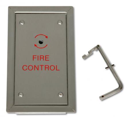
Drop Key and Switch (Photo: Videx) |
The operation of the switch may be via a break glass, Crescent switch, Yale keyswitch, triangle key, budget key, but is now most commonly via a drop key. Because the use of these over-ride systems has evolved over many years their actions can vary from one building to another. The most common effect is to over-ride all floor calling, to return the lift to the floor where the Fireman’s switch is, then to open the doors and the doors remain open. Control of the lift is purely through the lift cars buttons and pressure must remain on the button during operation.
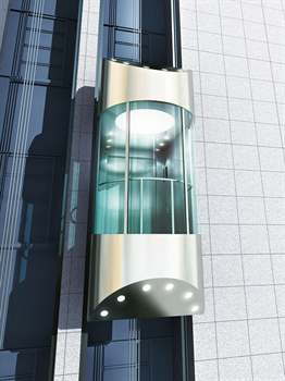
Scenic elevators
Photo: Kone Elevators |
These are a modern design of lift that may be internal or external to the building. The lift car is usually made of glass and may not be enclosed by a shaft. If it is in a shaft then the shaft will have at least one glass side. These lifts are designed to give the user a view of there |
The Fire Fighters Lift
It is most important to understand from the outset that “Unless specifically designed, and compliant with all the requirements” a lift is NOT a Fire Fighting lift.
HAVING A FIREMANS SWITCH DOES NOT MAKE IT A FIRE FIGHTING LIFT!!

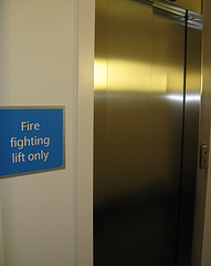
The BS approved signage marking a Fire fighting Lift (Photo : BSI)
A Fire fighting lift is a very specific design of lift with many additional built in safety features. Such lifts have been a design feature of some buildings since BS5655 (in the eighties). Their protection is covered in Approved Document B and currently the design standard for Fire fighting lifts is covered in En81 and its general requirements are:
Must conform to EN 81-1 or 2
Must serve every floor of a building
Minimum size is 8 persons (630 kg)
1100mm wide x 1400mm deep
or For Evacuation, 13 person 1100mm x 2100mm
Door must be minimum of 800mm wide
Must reach furthest floor from FSAL in 60 seconds.
Must have Built in Water protection from fire fighting run-off.
Must have self rescue facilities (an escape hatch and ladder)
Must have a communication system between the lift car and the FSAL.
Have fail safe (dual/backup) power supplies, installed in protected cable.
In its own dedicated protected lift shaft.
When its activated (put into fire fighting mode either by the Fire alarm system or operation by Fire service personnel) the lift Control system will:
Isolates all landing calls and cancels car calls
Lift car returns to FSAL and parks with doors open
Shaft and machine room lighting is switched on
It will now only function as:
Single call operation
Doors remain closed on arrival
Constant pressure control of doors
Communication device operative between Lift Car, machine room and FSAL
